|
|
|
| HT Cushyfloat™ |
|
| Features/Application |
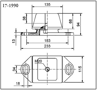
The HT Cushyfloat (High Thrust) Mounting has been developed to meet the increased torque output and higher thrust load requirements of many modern marine power units. By careful design of the r ubber section, relatively high degrees of flexibility in the vertical and lateral modes are combined with high stiffness in the longitudinal fore and aft direction, thereby affording good vibration isolation properties and minimum movement under thrust forces. |
The design incorporates bump and rebound control features which limit excessive movements under shock loading. The mountings have a high inbuilt tensile strength which renders them very suitable for the suspension of power units in lifeboat applications. |
The top metal cover gives protection against oil contamination and the protective finish resists corrosion attack. Two basic designs and different rubber compounds allow loads between 85 and 1070 kg to be accommodated. |
|
|
| All dimensions in mm |
Product No. |
Weight kg |
Rubber Hardness |
Kv static (kN/mm) |
Kv dync. (kN/mm) |
Max Vertical Load (kN) |
Max Comp‘n (mm) |
Min Vertical Load (kN) |
Min Comp‘n (mm) |
17-1990 |
6.2 |
45 |
1.6 |
1.85 |
5.6 |
4 |
1.47 |
1 |
17-1990 |
|
60 |
3.0 |
3.9 |
10.5 |
4 |
2.9 |
1 |
17-2182 |
3.4 |
35 |
0.4 |
0.42 |
1.37 |
5 |
0.83 |
3 |
17-2182 |
|
45 |
0.57 |
0.66 |
2.05 |
5 |
1.23 |
3 |
17-2182 |
|
55 |
0.96 |
1.2 |
3.33 |
5 |
2.00 |
3 |
17-2182 |
|
65 |
1.53 |
2.06 |
4.9 |
5 |
2.95 |
3 |
|
| Nominal Stiffness Ratios |
Product No. |
Vertical Kv |
Athwartship K lat |
Fore & Aft K long |
17-1990 |
1 |
0.25 |
9 |
17-2182 |
1 |
0.85 |
6 |
|
N.B. Stiffness values quoted refer to tangent stiffness at 5 mm static deflection for 17-2182 and at 4 mm for 17-1990 and are for guidance purposes only. |
Note ! For marine applications, maximum loads quoted refer to combined static and continuous torque generated forces. Data given overleaf shows variation in fore and aft stiffness depending on vertical loading. When horizontal forces due to propeller thrust are present, vertical loads should be reduced and our Marine Application Department consulted for advice. |
|