|
|
|
|
| Chevron Springs |
|
| Features |
Chevron Springs provide three modes of flexibility for axlebox primary suspensions. |
The suspension properties are achieved by fitting the springs in a vee formation and with shear and compression compliance within the rubber elements. Improved ride characteristics are provided with the advantages of simplicity, long service life and low maintenance costs. |
Abutting end plates can be produced in light alloy to match with similar material interfaces at the axlebox or vehicle frame. |
The included angle of the chevron plates can be varied between 90 deg. and 140 deg. at the design stage thereby allowing stiffness characteristics to be optimised to suit bogie designers. |
|
|
| Applications |
Metalastik® Chevron Springs are operating world wide in a diversity of service applications including LRV, Metro, Freight wagons, High Speed Passenger Coaches and Locomotives. Axlebox load capacities range from 16 kN to 120 kN and vertical deflections from 12 mm to 100 mm. |
|
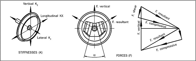
| Spring characteristics |
 |
|
The three modes of flexibility for axlebox suspension are shown here. Springs are fitted inclined at an angle to the vertical axis, loading the rubber layers in shear and compression.
|
| Values quoted for lateral and longitudinal stiffness may vary with vertical deflection. |
The longitudinal stiffness value applies when the elastic centre of the two Chevron springs is at the journal centre height. If the elastic centre is above or below the centre of the journal, the longitudinal stiffness at the journal will be less than the value quoted.
|
Metalastik® Chevron springs may be fitted to two bearing or single self-aligning bearing axleboxes. For stability with self aligning bearings, the elastic centre of the Chevron springs in their laden position should not be above the journal centre height. The temperature at the axlebox faces adjoing the Chevron springs should not exceed 60 degrees C.
|
| A typical force diagram is shown above. |
|
| |
| Installation |
 |
The vertical deflection (dz) may vary due to creep, Joule effect and stiffness tolerances. Shims (G) should be included for height adjustment. Shims (H) are sometimes necessary for accurate alignment of axles. |
|
| Spring fixings |
 |
|
 |
| Tolerances |
Tolerances at the adjoining faces should be as shown. |
|
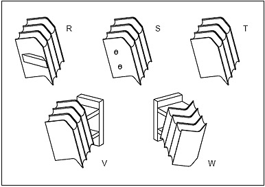
Springs can be supplied with alternative methods of location as shown in the diagram, namely with cross bar (R), dowel pins (S), or edge location (T). Location on the bogie frame is normally on the plate edge. Springs can be supplied with brackets for direct and easy fitting to the bogie frame (ref . figs V & W) |
| CLASSIFICATION |
Springs listed on the following pages are classified in the following ranking order : |
| 1) Chevron angle - 90°, 106°, 120° and 140°. |
2) Listings in each of the above groups are then ranked progressively in terms of deflection capacity followed by load capacity. |
| Footnote |
The Chevron springs listed are a selection from the Metalastik® range. New designs can be produced to suit special requirements, including bracketed versions. Stiffness values quoted are for preferred rubber hardness of 50 deg. shore but other hardnesses are available and installation included angles (α) may be varied to suit customer requirements. |
|
|
|
|
| |
| |
|
|
|