|
|
|
| Spherilastik Bearings |
|
| Features / Applications |
A heavy duty flexible bearing which combines highload carrying capacity with the ability to accommodate torsional and angular movements in all planes without lubrication and metal-to-metal wear. |
Spherilastik bearings with through holes or solid centre members are available in a range of sizes as detailed in this leaflet. |
Typical uses include traction and braking reaction rods for rail, road and off-road vehicles, hydraulic damper fixings and other applications where a high duty bearing of compact size is required. |
|
|
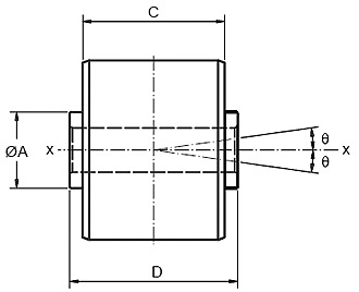
| Centre Bore |
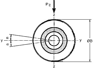 |
The diagram shows overall and fitting dimensions only. It is recommended that a drawing of the product is obtained before ordering. |
|
|
|
Part No. |
13/1316 |
13/1962 |
13/2201 |
13/2047 |
13/2108 |
13/1295 |
13/2106 |
Pz kN |
34 |
34 |
34 |
35 |
53 |
53.5 |
58 |
Kz MN/m |
70 |
70 |
70 |
32 |
83 |
83 |
100 |
α° |
8 |
8 |
8 |
10 |
8 |
8 |
8 |
Kxx kNm/rad |
0.9 |
0.9 |
0.9 |
3.2 |
2.6 |
2.6 |
2.8 |
θ |
6 |
6 |
6 |
8 |
6 |
6 |
6 |
Kyy kNm/rad |
0.9 |
0.9 |
0.9 |
2.9 |
2.6 |
2.6 |
2.8 |
A mm |
25.4 |
25 |
25.4 |
38.1 |
41.3 |
41.3 |
28.6 |
B mm |
66.7 |
66 |
66.7 |
104.8 |
90.5 |
90.5 |
90 |
C mm |
47.6 |
48 |
47.6 |
76.2 |
101.6 |
70 |
70 |
D mm |
54 |
54 |
54 |
82.6 |
65 |
73.2 |
76.2 |
Mass weight, kg |
0.84 |
0.83 |
0.41 |
3.2 |
1.5 |
2.2 |
1.8 |
|
|
| General guidance notes for selection: |
| 1. Properties quoted for the components in this leaflet relate to continuous steady loading or deformation conditions. |
| 2. For continuous dynamic cyclic loading or deformation, the maximum values should be reduced to approximately 30% of the figures quoted, depending on frequency. |
| 3. For medium and low incidence loading and deformation, the tabled values may be increased up to 2 to 3 times. |
| 4. Combined stressing in the different modes and the effects of stress reversals may require a more critical assessment. |
|
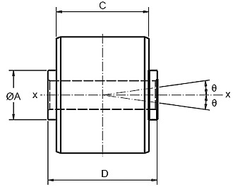
| Centre Bore |
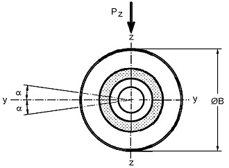 |
The diagram shows overall and fitting dimensions only. It is recommended that a drawing of the product is obtained before ordering. |
|
|
|
|
Part No. |
13/1006 |
13/1285 |
13/1180 |
13/0894 |
13/1680 |
13/1339 |
13/1990 |
Pz kN |
58 |
78 |
110 |
180 |
220 |
400 |
425 |
Kz MN/m |
93 |
90 |
100 |
100 |
260 |
350 |
470 |
α° |
8 |
8 |
10 |
9 |
6 |
7 |
7 |
Kxx kNm/rad |
2.8 |
4.5 |
7 |
30 |
15 |
26 |
21 |
θ |
6 |
7 |
6 |
8 |
5 |
6 |
6 |
Kyy kNm/rad |
2.8 |
3.8 |
6 |
20 |
13 |
20 |
18 |
A mm |
28.6 |
38.1 |
44.5 |
76.2 |
50.1 |
114.3 |
60 |
B mm |
90.5 |
104.8 |
127 |
200 |
127 |
200 |
150 |
C mm |
70 |
76.2 |
101.6 |
152.4 |
101.6 |
152.4 |
120 |
D mm |
54 |
54 |
54 |
82.6 |
65 |
73.2 |
76.2 |
Mass weight, kg |
2.2 |
3.4 |
6.6 |
21.9 |
6.3 |
19.4 |
11.5 |
|
|
| General guidance notes for selection: |
| 1. Properties quoted for the components in this leaflet relate to continuous steady loading or deformation conditions. |
| 2. For continuous dynamic cyclic loading or deformation, the maximum values should be reduced to approximately 30% of the figures quoted, depending on frequency. |
| 3. For medium and low incidence loading and deformation, the tabled values may be increased up to 2 to 3 times. |
| 4. Combined stressing in the different modes and the effects of stress reversals may require a more critical assessment. |
|
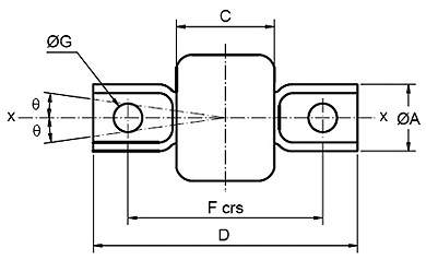
| Trunnion Type |
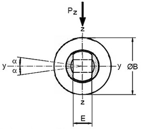 |
The diagram shows overall and fitting dimensions only. It is recommended that a drawing of the product is obtained before ordering. |
|
|
|
|
Part No. |
13/2092 |
13/2202 |
13/2203 |
13/2181 |
13/2192 |
13/2033 |
13/2223 |
Pz kN |
12 |
34 |
34 |
58 |
58 |
75 |
80 |
Kz MN/m |
34 |
70 |
70 |
90 |
90 |
150 |
100 |
α° |
8 |
8 |
8 |
10 |
8 |
8 |
8 |
Kxx kNm/rad |
0.17 |
0.7 |
0.7 |
2.8 |
2.8 |
2.8 |
4.5 |
θ |
6 |
6 |
6 |
6 |
6 |
6 |
7 |
Kyy kNm/rad |
0.2 |
0.9 |
0.9 |
2.8 |
2.8 |
2.8 |
3.8 |
A mm |
30 |
35 |
35 |
48 |
48 |
40 |
50.5 |
B mm |
45 |
66.7 |
66.7 |
90.6 |
90.6 |
84 |
104.8 |
C mm |
35 |
47.6 |
47.6 |
70 |
70 |
65 |
76.2 |
D mm |
105 |
120 |
126 |
190 |
170 |
155 |
170 |
E mm |
12 |
20 |
20 |
30 |
30 |
20 |
30 |
F mm |
75 |
90 |
96 |
140 |
130 |
120 |
130 |
G mm |
13 |
13 |
17 |
20.5 |
20.5 |
16.5 |
19 |
Mass weight, kg |
0.47 |
1.14 |
1.02 |
2.8 |
3 |
2.8 |
5.8 |
|
|
| General guidance notes for selection: |
| 1. Properties quoted for the components in this leaflet relate to continuous steady loading or deformation conditions. |
| 2. For continuous dynamic cyclic loading or deformation, the maximum values should be reduced to approximately 30% of the figures quoted, depending on frequency. |
| 3. For medium and low incidence loading and deformation, the tabled values may be increased up to 2 to 3 times. |
| 4. Combined stressing in the different modes and the effects of stress reversals may require a more critical assessment. |
|
| |
| Control links |
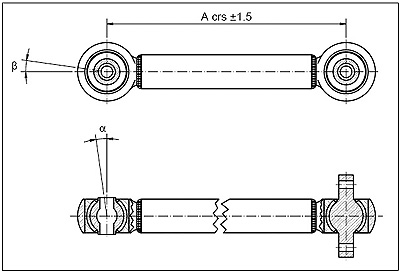 |
Features/Applications
|
A range of Control Links incorporating Spherilastik Bearings is available and typical sizes are listed below. Further details are available on request. |
|
|
|
Part No. |
Spherilastik Part No. |
Type |
A1mm |
Nominal P. max kN |
β |
α |
Mass weight
|
Degrees |
Degrees |
kg |
13/2233 |
13/2192 |
2 |
490 |
58 |
6 |
8 |
12 |
13/2235 |
13/2107 |
2 |
644 |
58 |
6 |
8 |
14 |
13/2154 |
13/1006 |
1 |
673 |
58 |
6 |
8 |
15 |
13/2280 |
13/1006 |
1 |
720 |
58 |
6 |
8 |
16 |
13/2369 |
13/2192 |
2 |
1315 |
58 |
6 |
8 |
27 |
|
| Properties quoted are for 60H rubber compound |
| General guidance notes for selection: |
| 1. Properties quoted for the components in this leaflet relate to continuous steady loading or deformation conditions. |
| 2. For continuous dynamic cyclic loading or deformation, the maximum values should be reduced to approximately 30% of the figures quoted, depending on frequency. |
| 3. For medium and low incidence loading and deformation, the tabled values may be increased up to 2 to 3 times. |
| 4. Combined stressing in the different modes and the effects of stress reversals may require a more critical assessment. |
|